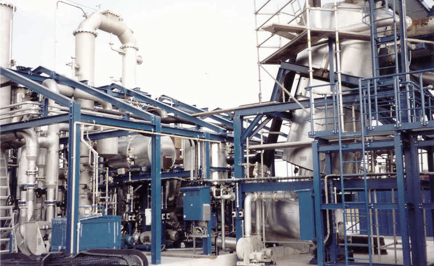
The technology
UNIQUE PATENTED TECHNOLOGY
Key Challenges in pyrolysis:
- Limited type of waste accepted
- Low tolerance to acidic waste types
- High temperature & pressure
- Clogging
- High maintenance cost
- High water consumption
- High level of emissions
- 1-2 trains with high operating cost
- No option to upgrade to the production of Hydrogen rich syn. gas.
- Limitation in application toward existing waste management operation.
Main Improvements and uniqueness:
- Most types of waste accepted
- Simple design, standardized components
- Modularized design with high redundancy
- Proprietary technology transforms waste into hydrogen rich gas
- Reasonable water consumption
- Co2 capture – Low emissions
- Low maintenance costs
- Low temperature and pressure
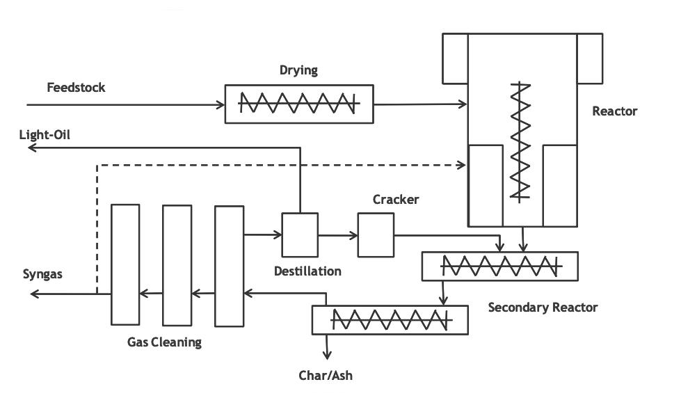
The plant consists of the following sections
- Feedstock storage
- Drying
- Reactors
- Secondary Reactors
- Cracking-Reactors
- Gas cleaning
- Auxiliary systems
Feedstock storage
The feedstock storage is used for buffering enough feedstock to operate the plant independent of a continues delivery. The feedstock is delivered by trucks. The equipment for material handling in the storage is configured for specific requirements of each project.
Drying
In the dryers the feedstock is indirectly heated with the exhaust gas of the reactors, and thus the moisture is reduced. The drying system is also used to convey the feedstock from the level of the storage to the feeding of the reactors. Furthermore, the dryers implement an air-look between the gas-containing plant sections and the atmosphere. The drying system is implemented as a cascade consisting of the feeding system and the drying screws (screw conveyers with heating jacket). The cascade also contains flaps to encapsulate the stages.
Main Reactors
Within the main reactors the chemical conversion of the dried feedstock into a gas or hydrocarbon vapor takes place. This conversion covers the cracking reaction, the depolymerization, the gas reaction and the conversion reaction. These chemical processes take place in the different chambers of the reactor, at slightly positive pressure and temperatures between 400°C and 800°C in the absence of air and oxygen. It implements descending gasification.
The feedstock enters the reactor via the feeding zone into the mixing chamber. The mixing chamber and the descending high temperature chamber are indirectly heated via the heating jacket. Heating is provided by burners, which can use cleaned syngas or natural gas as fuel. The feedstock is moved within the reactor by a screw and rotors. The partially converted feedstock and the raw gas are passed into the following system. The exhaust gas from the heating jacket is used to heat the drying and other systems.
Secondary Reactors
In the secondary reactors the partially degraded material is kept at high temperature over a residence time of about an hour. This high residence time ensures a complete conversion of the hydrocarbons of the feedstock. Furthermore, the raw gas from the main reactors passes the char bed in the high temperature zone of the secondary reactor. Thus the reaction time for the shift reaction is increased and short-cuts of the raw gas are avoided. The structure of the post-reactors is similar to the main reactors. In the reactor cascade a char-ash mixture is produced. This is cooled within the char outlet and discharged into containers.
Crack Reactors
The cracker system is used for the conditioning and the cracking of condensates from the gas cleaning. From the cracker system these components are fed back into the main reactors. The cracker system provides a fast control loop for the amount of syngas produced.
Gas cleaning
The first stages of gas cleaning are used for removing tars, oils and dust particles from the raw gas stream, and for cooling the raw gas stream. The following scrubbing stages are required for the removing of contaminations from the syngas.
The syngas passes within the gas cleaning several processes each with defined process parameters. Liquid components and contaminations are removed, bound and cooled. An integrated blower conveys to the syngas through the gas cleaning. The cleaned syngas is delivered to the consumer. A partial stream is used to heat the reactors.
The liquid components separated within the gas cleaning are buffered, cracked and fed back into the reaction process or outlet as product.
The scrubber systems are composed of scrubbers, tanks, pumps, separators, heat exchangers, etc. A medium is used in the work cycles of the scrubbers. This binds the condensates and contaminations from the syngas and cools the syngas in stages. The condensates are discharged with the media. The medium consists of olefins, aromatics, paraffins and similar substances, as well as dust particles and water.
The standard configuration implements five scrubbers. The number of scrubbers is determined depending on the feedstock characteristics. The discharged medium is supplied to the separators, the cracker system or the wastewater treatment depending on the contained substances. From the system, the light oil product can be discharged, which consists of paraffins, olefins and aromatics.
The equipment relevant for save and clean operation is implemented redundantly.